The value of the compressor is great both in terms of functionality and in terms of the cost of the metal, regardless of how you look at it. The engine can be used to make a pump for tire service, painting or a refrigeration system.
If the engine is not working and its power is relatively low, then there is no point in repairing it. The device consists of ferrous metal (housing, gear components) and copper (motor winding, tubes). The average weight is from 5 to 10 kilograms, while the weight of expensive copper can reach 1.5 kilograms.
Disassembly without using a grinder
In order to separate the ferrous metal from the copper, you must first disassemble the compressor. Let's figure out how to disassemble the device without using an angle grinder (grinder), because an angle grinder is a relatively dirty tool; there will be a lot of dust, sparks, noise in the workplace, oil poured inside (the cutting disc will splash materials around it).
Unfortunately, the body is a monolithic metal product containing a series of welds created using automatic welding.
Therefore, you can avoid the grinder only with a hacksaw. The thickness of the metal can be more than 3 millimeters. As for the rotor and stator, an angle grinder is not required; it should not be used at all stages of disassembly.
In the welding area you need to make a cut, drain the oil and “walk” along the entire seam.
The cut should be small to avoid splashing. Oil should flow out slowly through the small hole.
Cutting should be done carefully, without haste; If you work with a hacksaw, you should monitor the sharpness of the saw (it is better to stock up on spare blades). The motor windings are visible under the cut cap. After unpacking the case, you can discover the causes of the device malfunction. In our case, the cause is a burnt-out winding.
Classification of compressors in refrigeration equipment
Despite the general principle of operation, the design of the mechanisms may differ significantly. The classification is made according to the principle of action into three subtypes:
- Dynamic. In such devices, the refrigerant is circulated under the influence of a fan. Depending on the design of the latter, they are usually divided into axial and centrifugal. The first ones are installed inside the system, and during operation they build up pressure. Their operating principle is the same as that of a conventional fan.
Axial compressor
The latter have a higher efficiency due to an increase in kinetic energy under the influence of centrifugal force.
Cross-section of a centrifugal compressor
The main disadvantage of such systems is the deformation of the blades due to the torsion effect that occurs under the influence of torque. Dynamic settings are not used in household equipment, so they are not of interest to us.
- Volume. In such devices, the compression effect is produced using a mechanical device driven by an engine (electric motor). The efficiency of this type of equipment is much higher than that of screw units. Widely used before the advent of inexpensive rotary devices.
- Rotary. This subtype is distinguished by its durability and reliability; modern household units use just such a design.
Considering that the last two subtypes are used in household devices, it makes sense to consider their structure in more detail.
Compressor disassembly options
There are two ways to disassemble: knocking out and cutting the rear cap. Thin-walled models come out of the case very easily when knocked out; older models are almost impossible to knock out. If all the oil has been previously drained, you can immediately begin sawing without making test cuts. Use a hacksaw to cut off the “back cap”.
One tube will not allow the cap to come out of the body; it is enough to cut it with a hacksaw. After disassembly, you can see the entire engine from the inside.
Screws are visible, unscrewing which allows you to release the entire mechanism and remove it from the case.
Without cutting off the ends of the compressor, it is impossible to disassemble it, since all compressors are manufactured in the form of a monolithic structure. Both sides of the shell are welded, and the screws that can solve the problem are located under a layer of thick metal and welds.
After unscrewing the support bolts, the motor, gearbox, stator and rotor are revealed. To remove copper windings and cores, do not use a grinder and cut the shell from the inside. Everything is held on with screws and can be easily disassembled.
Opening the refrigerator compressor with your own hands
Object of autopsy:
The task is to preserve the flanges of the casing halves for further tightening. The difficulty is the semicircular shape of the welded joint.
At the Forum, the option of grinding the grinder with a grinding disc was proposed, but after this the dimensions of the flange will be greatly reduced. It will be more difficult to tighten. It is very difficult to cut straight through the joint - the disc will slide off the top of the roller. “Improved” my ratsukha. Persons with unstable mental health should not read further!
I made a set of “remnants”. The kind that normal “Bulgarians” throw away. Without considering myself one of those, I accumulated them... in general, a lot. Therefore, I found it easily: 2 cheeks, 2 spacers, the actual cutting one. The difficulty is that the thickness of the package is greater than what can be centered with a standard Bulgarian nut. I had to “by eye”...
I made a groove at the top of the roller along its entire length:
Next, I cut through 1mm of soap (so as not to damage the patient’s intestines) until the casing is completely halved.
All. No matter how sick my grandmother was, she still died.
By the way, after this work there are remnants left, which I will throw away without pity!
Although... You can get some good spacers... Let them sit for a while.
PS: such an opening takes much more time than in the case when you just need to remove the MK from the casing without saving the latter.
Disassembling the compressor from the refrigerator
You can disassemble the compressor using a grinder. If you cut off the top of the cap, you can see a vertically located engine and a block with one cylinder. The freon tube is bent into a spiral so that there is play in the tubes during vibration. If the tubes are tightly secured, vibration will cause them to break.
Cutting the top will do nothing to remove the engine, so you can cut off the bottom of the compressor. The bottom view gives an idea of the cooling of the entire compressor during operation. At the bottom there is a tube through which freon is circulated, cooling the engine itself. In addition to the tube, shock-absorbing fasteners on which the engine is mounted are visible on the sides. As a result of the fact that the engine converts the rotating movement of the shaft into the translational movement of the compressor piston due to the eccentric on the engine shaft, vibrations occur in the entire mechanism. To compensate for vibration on the shaft next to the eccentric, metal was selected in such a way as to level the masses during rotation, balancing the entire system. The engine is also placed on springs placed on pins. Nuts are not used. The engine is limited at the top by a cap. The motor connection connector is also located here.
The first cut went through the bottom of the cap and was useless for disassembly, just like the second cut. To remove the engine from the housing, you need to make a cut under the head or in the middle of the tank. The removed engine is covered in oil. The windings are clearly visible on it - working and starting. The starting winding is made of thick wire and has low resistance. The working winding is the exact opposite of the starting winding: small diameter and high resistance.
After removing the casing, the engine and compressor present a deplorable sight.
By removing the four screws holding the compressor housing in place, the compressor and motor can be separated. The eccentric and balance plate are visible on the engine. On the compressor you can see the piston itself with a hole for the eccentric, which pumps freon into the system.
There are only 4 chambers on the compressor. Through some, freon is taken from the system, through others, with the help of a piston, freon is compressed and pushed back into the system.
This is roughly how a refrigerator compressor works.
A single-phase electric motor has two windings connected in series with an output from a midpoint.
To start such an engine, you need to apply either phase or zero to 0 common, and either zero or phase to 1 start and 2 working, respectively. In other words, the voltage between pins 1 and 0 should be 220 V, between pins 0 and 2 - 220 V, and between pins 1 and 2 the voltage should be zero. If the voltage is applied correctly, the engine will jerk and the rotor (the part of the engine that rotates) will begin to rotate. The direction of rotation depends on which end of the working winding is connected to the common terminal. In a refrigerator, it is impossible to start the engine in the other direction, because the common terminal is located inside the hermetically sealed compressor.
After the rotor begins to rotate, you must immediately turn off the starting coil. Otherwise, the motor will overheat and the winding insulation will burn out, which will cause an interturn short circuit and damage the motor. To disconnect the starting coil, it is enough to disconnect pin 1, then the voltage between pins 0 and 2 is 220 V and the engine will not stop.
The starting coil is only needed to start the engine and is not needed at all while it is running. To accurately determine the health of the engine, use an ohmmeter; the resistance values are visible on the device.
The starting current of the refrigerator compressor motor is 4.8 A, and the operating current is 1.02 A. At the same time, the resistance of the starting winding is 13.1 Ohms and the operating winding is 47.5 Ohms. Small fluctuations of 0.5 ohms are acceptable. It should be taken into account that the more powerful the refrigerator, the higher the resistance and current values will be.
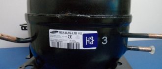
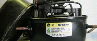
All manufacturers see their compressors differently and the starting winding is not always higher in resistance than the working winding. Many foreign manufacturers have a working winding larger than the starting winding. This difference is only a few ohms. It all depends on the manufacturer and the specific compressor. On the compressor label you can see three connection points similar to the compressor connector.
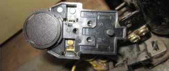
- C - COM, means the point of connection of two windings, i.e. center point
- S - START, starting starter winding
- R - RUN or M - MAIN, working winding.
For comparison, I present the resistance of the compressor windings of refrigerators from different manufacturers.
The engine is controlled by a starting relay. The relay is located in a plastic box to the right of the installation junction box.
When a single-phase electric motor is turned on, a large starting current flows through the working winding. The starting current is 3-7 times the rated current of the motor, it lasts only for a while until the motor rotor begins to rotate and reaches the rated speed. The relay coil is connected in series with the working winding of the motor, so when the current is high, a magnetic flux will appear in the coil, which will push the coil core up. At the end of the core there is a contact plate that connects the starting winding of the motor to the network. As soon as the rotor rotation speed reaches the planned value, the starting current in the working winding will drop, the magnetic flux in the starting relay coil will drop and the plate will lower, disconnecting the starting winding of the engine from the network.
If the engine overheats, that is, if the engine rotor does not have time to pick up rotation speed, or if the engine itself is faulty, an emergency shutdown of the electric motor from the network is provided. The protection is made in the form of turns of nichrome wire. Nichrome is an alloy of the metals nickel and chromium. When current is passed through it, the nichrome heats up and releases heat, but does not burn. That is why most electric heating devices contain this metal.
When large starting currents flow, nichrome heats the bimetallic plate located underneath it, the plate heats up and bends, disconnecting both motor windings from the network. After some time, the nichrome will cool down, the bimetallic plate will return to its normal position and the relay will restart the refrigerator again. If you have a refrigerator at your dacha and during a thunderstorm, or when a welding machine is working nearby, the refrigerator growls and does not turn on, then know that there is not enough voltage for the rotor to gain the required speed and the protection is triggered.
The start and shutdown of the refrigerator is controlled by a temperature sensor, which gives the start command by applying a potential to the common terminal of the motor. The temperature sensor is a sealed tube filled with gas, a housing with a rod for regulating the temperature at which it operates and leads for connecting wires.
Sometimes two sensors are installed - one on one camera, and the second on the second camera. Or the second sensor is used for the defrosting function, which means that the refrigerator will not turn on until it is completely defrosted.
When assembling and connecting all wires, you must observe the correct electrical diagram. For clarity, all wires are marked. 220 V (brown and blue) comes from the network. The compressor motor is also powered by 220 V. Power is supplied to the motor from the brown power wire through the blue wire (3). The second wire to the engine is taken from the brown network wire through the gray wire to the temperature sensor, the output from the sensor is a white wire connected to the black wire (0). To check whether the compressor is working without a temperature sensor, you need to apply a voltage of 220 V to the blue (3) and black (0) wires suitable for the start relay.
For those who are especially meticulous and don’t have a start relay, you can take three pieces of wire. Connect one to terminal (0) on the compressor plug, the second to the end of the working winding (2) and the third to the end of the starting winding (1). The free ends of the wires (1) and (2) must be connected together. It is advisable to equip the wire to terminal (1) of the compressor with a toggle switch, but it is possible without it. Now you need to apply power. Insert the wire to terminal (0) into one contact of the socket, and the wires connected together to terminals (1) and (2) into the other. Almost immediately you need to disconnect the wire to terminal (1) from the network. The relay response time is approximately 0.5 s. It’s better to disconnect it with a toggle switch, but you can also use side cutters with insulated handles. The compressor will start working. To start it again you will need to cut the wire again. There are never too many wires, so if there is no relay, assemble a switching circuit through a toggle switch or circuit breaker. The engine runs on 220 V, which is supplied to contacts (0) and (2). Just to start, you should connect to contact (1) the same wire that goes to contact (2).
Almost all single-phase motors can be started from a capacitor. The fact is that single-phase motors operate from brushes (one stator winding and one armature), starting relays (two unequal stator windings) and a capacitor (two stator windings). The capacitor is connected between the ends of both windings according to the diagram below.
On average, the capacitor capacity is taken at the rate of 22 μF per 1 kW of engine power. It turns out that a 155 W refrigerator motor needs a 3 µF capacitor. You need a paper capacitor. The supplied 160 V capacitor did not heat up or explode, but it did crack, so we are looking for a capacitor of at least 250 V. The heating of the windings will serve as an indicator of operation. The reason why a relay is used to start the refrigerator compressor is higher starting reliability. And indeed, during tests, the engine started when the power cables were switched sharply, but when started using a switch, sometimes the engine did not rotate, but hummed. This is due to the fact that a starting capacitor was not used. The starting capacitor is connected in parallel with the working capacitor and only when the engine starts. The capacity of the starting capacitor is 3 times higher than the capacity of the working capacitor.
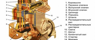
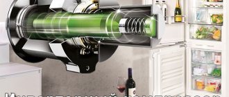
Refrigerator compressor device
A piston compressor is most often installed in a household refrigerator.
It consists:
- from a sealed metal case;
- start relay;
- motor;
- vertical crankshaft;
- piston;
- valves for pressure regulation.
The mechanics of its operation are simple and similar to an internal combustion engine. The starting relay closes and the unit motor starts. A piston attached to the crankshaft moves and causes freon to circulate.
Important! When a compressor breaks down, it is not repaired, but replaced, because it is difficult to open the housing without depressurizing the unit.
Video: how to disassemble a compressor from a refrigerator
How to disassemble a compressor from a refrigerator
Watch this video on YouTube
Do you want to understand better than others?
- Refrigerator compressor connection diagram - step-by-step instructions with photos and videos - Refrigerator compressor connection diagram will be needed if any malfunction occurs in the device. If you have the necessary knowledge and experience, the work can be done...
- DIY vacuum pump from a refrigerator compressor. Topic: Vacuuming with your own compressor - What is a vacuum pump? A vacuum pump, in principle, is a fairly simple design. The principle of its operation is pumping air from a given volume. For pumping, of course...
- Removing and Disassembling a Refrigerator Door - How to Disassemble a Refrigerator Door to Re-Hang It on the Other Side At the very top of the refrigerator, above the freezer door (you may need a ladder), remove two...
- How to check a refrigerator compressor. How to check a refrigerator compressor - step-by-step instructions - How does a refrigerator work and what place does the compressor occupy in it? The principle of operation itself can be divided into two main stages: At the first stage, freon gas ends up in…
- Self-removal and replacement of the refrigerator door handle: step-by-step instructions with photos - General instructions for removing the refrigerator handle The process of removing the handle is quite simple and does not cause difficulties even for beginners. Don't forget to take precautions...
Briefly about the types of equipment
Based on the operating principle, this equipment can be divided into four types:
- Steam ejector, the coolant is usually water. Used in various industrial processes.
- Absorption, for work it uses not electrical, but thermal energy.
- Thermoelectric, based on Peltier elements, wide application remains questionable due to low efficiency (detailed information about these devices can be found on our website).
- Compressor.
It is the latter type of equipment that is widely used in household and industrial units.