A big request to readers is not to consider the first paragraph a journalistic technique...
Recently, my “Home-made” amplifier began to jam a little on one channel, and I had to get serious about checking the details. It turned out that the whole issue was a low-quality capacitor at the input.
After the repair was completed, I was persuaded to temporarily borrow this amplifier with speakers for “events” (it was just the holidays). What can you do at home when there is nothing to connect to the sound card output, but you want to listen to music or just play another shooter (currently “Call of Duty”)?
So I took out of the closet the fairly dusty Cheburashka speakers that I had once used. Their price was something like 300 rubles, and they reproduced music with appropriate quality. So after “high-quality” sound (a good amplifier + more or less normal speakers), it became simply unbearable to hear the cardboard sounds made by the stunted little ones.
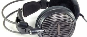
But there was still a headphone output on the Cheburashkas. Okay, so it's time to use the headphones. In stores, among all sorts of different “products”, I came across a headset from SONY CD-268M.V.
Of course, connoisseurs of quality will frown with displeasure - yes, the truth is yours, because the price of these “burdocks” is about 10 USD, and not 100... But compared to the screams of “buttons” for 30 rubles, this was “Sound”.
Although, of course, it’s still far from “SOUND” (the Cheburashkas were noticeably loud...).
Headphones could be connected directly to the output of the sound card, but one question arose - what kind of load are these outputs actually designed for?
The fact is that distortion measurements are almost always made when the output of the sound card is loaded onto the input of the measuring device, and its input resistance is unlikely to be 32 Ohms. But as the load resistance decreases, the current increases, and now as the volume increases, distortion increases - look at the characteristics of any microcircuit - a low-frequency amplifier (graphs are in almost every description).
It turns out that when connecting headphones, the sound card is unlikely to be able to provide a high standard of sound quality and fully reveal its potential. (Or will it still be able to?)
So the idea came to build an amplifier specifically for connecting headphones - after all, the homemade amplifier does not have a special jack (the circuit design is such that ordinary headphones simply cannot be connected there). There were quite a lot of schemes in magazines and on the Internet, but only four were chosen.
The quality of their “sound products” increases gradually, and the complexity of assembly practically does not increase. I hope many music lovers and gamers will find useful information here. And the wives will be able to take a break from the music and noise... (Only now it will be much more difficult for them to shout to you.)
Attention! Constant use of headphones at maximum volume leads to permanent hearing loss! Ministry of Health warns!
Scheme one, simple
The headphone amplifier circuit is quite simple. (Author - Valenty Svyaty, Practyczny Elektronik No. 2/2000, p. 4–6.) Actually, which, with a supply voltage of 9 Volts, can develop up to 1 W at a load of 8 Ohms. The microcircuit operates normally at loads up to 4 ohms and, with an output power of 150 mW, provides a harmonic coefficient of no more than 0.2%. This means that when working with headphones, the amplifier will not overwork, it will not get very hot and will not distort the sound.
The main feature of this circuit is automatic power on/off. When an audio signal is applied to the input of the amplifier, the voltage at the output of the detector on diodes VD1, VD2 becomes sufficient to open transistor VT2, which then opens transistor VT1, through which the supply voltage passes to the microcircuit.
The amplifier is powered by a 9-volt battery (Krona, for example). If there is no sound signal, the voltage at the detector output decreases to zero, the transistors close and the microcircuit is de-energized. The headphone amplifier is operational at a supply voltage of 1.8 to 15 Volts.
Naturally, if you do not suffer from forgetfulness, you can throw out the “extra” parts from the circuit (detector and transistor switch) and install a simple switch in the power circuit.
Ultra-linear Class A amplifier
Amplifier version based on domestic transistors
Author: AKA KASYAN
In fact, I didn’t come up with anything new, I just wanted to build this amplifier for a long time, but on many resources the reviews about it were not very good.
Unfortunately, I was unable to find photos of the completed amplifiers. As a rule, there were only discussions on the forum pages and I had no choice but to repeat the design. There are very few reviews about the scheme, mostly only negative. Complaints are mainly about low current consumption, too distorted output signal, etc.
First, all the optimal replacements for transistors were found. All transistors were used domestically. It was not possible to etch the board, so as always, the breadboard came to the rescue.
The entire circuit was assembled on the board, and the output transistors were soldered through wires to the main board. At first I used KT805 transistors for the output stage, then 819 and settled on KT803A - the best option for this circuit.
The circuit was planned for a standard 4 Ohm speaker, so some circuit ratings need to be selected to suit your needs. The output capacitor is 3300 uF with a voltage of 16-50 volts, the input capacitor is to taste (from 0.1 to 1 uF). For power supply I used a battery from an uninterruptible power supply, with it the amplifier develops up to 8 watts, this is pure power, without wheezing, distortion or hum.
During my practice I have collected many power amplifiers. A year ago, the standard of sound for me was STK microcircuits, then the Lanzar circuit was repeated and it did not give up its position for a long time, but a few days ago this amplifier came out on top, leaving the famous Lanzar behind.
A wide range of reproducing frequencies is another advantage of this circuit, although the amplifier will not be able to reproduce frequencies below 30 Hz. The amplifier is designed for wideband acoustics, and for high-quality sound, you first need high-quality speakers. Although many may not agree, I highly recommend using domestic 5 - 10 GDSh heads with a paper or foam suspension. After pure class “A”, even the music center will not sound as good as before.
The output transistors of the amplifier do not heat up as badly as was said in some forums; personally, without a heat sink, they worked for 10 minutes at maximum volume, the temperature did not exceed 70-80 degrees.
The strange thing is that the amplifier is of such high quality that without an input signal there is no noise or hum in the speakers, as if the amplifier is turned off and turns on only when a signal is supplied to the input.
It is not recommended to increase the supply voltage to more than 20 volts; at 18 volts, the amplifier showed 14 watts - pure sinusoidal power, but consumed 60 watts... for class “A” this is quite normal. In the future we plan to build another channel, I really liked this amplifier, even the stereo system sounds bad next to it.
List of radioelements
| Designation | Type | Denomination | Quantity | Note | Shop | My notepad |
| T1 | Bipolar transistor | KT361G | 1 | 2N3906 | Search in the Otron store | To notepad |
| T2 | Bipolar transistor | KT801A | 1 | KT630D, KT602A, 2N697 | Search in the Otron store | To notepad |
| T3, T4 | Bipolar transistor | KT803A | 2 | MJ480 | Search in the Otron store | To notepad |
| C1 | Electrolytic capacitor | 100 µF | 1 | Search in the Otron store | To notepad | |
| C2 | Capacitor | 0.22 µF | 1 | Search in the Otron store | To notepad | |
| C3 | Electrolytic capacitor | 220 µF | 1 | Search in the Otron store | To notepad | |
| C4 | Electrolytic capacitor | 470 µF | 1 | Search in the Otron store | To notepad | |
| C5 | Electrolytic capacitor | 3300 µF | 1 | Search in the Otron store | To notepad | |
| C6 | Capacitor | 0.1 µF | 1 | Search in the Otron store | To notepad | |
| R1 | Resistor | 39 kOhm | 1 | Search in the Otron store | To notepad | |
| R2 | Variable resistor | 100 kOhm | 1 | Search in the Otron store | To notepad | |
| R3 | Resistor | 100 kOhm | 1 | Search in the Otron store | To notepad | |
| R4 | Resistor | 220 Ohm | 1 | Search in the Otron store | To notepad | |
| R5 | Resistor | 2.7 kOhm | 1 | Search in the Otron store | To notepad | |
| R6 | Resistor | 8.2 kOhm | 1 | Search in the Otron store | To notepad | |
| R7 | Resistor | 47 Ohm | 1 | 0.5 W | Search in the Otron store | To notepad |
| R8 | Resistor | 180 Ohm | 1 | 1 W | Search in the Otron store | To notepad |
| R9 | Resistor | 2.2 kOhm | 1 | 0.5 W | Search in the Otron store | To notepad |
| R10 | Resistor | 10 ohm | 1 | 1 W | Search in the Otron store | To notepad |
| Add all | ||||||
Attached files:
- ynch_a.rar (25 Kb)
Tags:
- ULF
- Sprint-Layout
Scheme two, advanced
A headphone amplifier circuit called “Volume and tone control unit for stereo headphones” caught my eye. (Author - Andrzej Kosminski, Hobby Elektronik, No. 2/2000, pp. 48–49). The volume and tone controls themselves are made on the A1 chip - TDA1524A in a typical switching circuit. (This was written in the magazine; in the original description of the microcircuit, the circuit is slightly different. But here the circuit is presented in its “published” form).
A “powerful” amplifier capable of driving low-impedance headphones is assembled on the dual operational amplifier A2.
Depth of volume control (R2) from –80 to +21 dB, bass tone (R4) +/- 12 dB at a frequency of 100 Hz, treble tone (R5) +/- 10 dB at a frequency of 10 kHz.
The maximum input voltage is no more than 2.5 Volts, supply voltage 12 Volts, current consumption 40 mA. The adjusting resistors should be 47 kOhm with a linear dependence of the change in resistance on the angle of rotation of the engine (the so-called group “A”).
There shouldn't be any difficulties in manufacturing. If you want to power the amplifier from a +12 Volt source from the computer's power supply, you will have to take measures to protect against interference in the power circuits (in the same way as car radio manufacturers do - they install special filters).
Fans of shooting games can limit themselves to these designs, but music lovers are encouraged to read the text further.
Simple Headphone Amplifier Designs
For radio amateurs, the domestic industry produces the Gamma radio designer, by purchasing which the user can easily make a good external headphone amplifier with his own hands (see photo and diagram in the figure).
Fig.1. Amplifier circuit "Gamma"
Fig.2. Amplifier "Gamma" assembled
It is suitable for both low-impedance and high-impedance headphones, is assembled on a single chip such as NME5532 or OPA2134 (depending on the version), is distinguished by an ultra-linear amplitude-frequency response (AFC) and provides the following technical parameters: frequency range (-1 dB ) – 8-400000 Hz, nonlinear distortion – 0.001-0.002 percent . The delivery set includes colorfully illustrated step-by-step instructions, using which not only an experienced, but also a novice radio amateur can assemble and configure the amplifier.
A good result can be obtained by assembling a similar headphone amplifier based on the Chinese-made “Shareconn Hi-Fi 47 two-channel amplifier” radio constructor. You can see the assembly process by watching the video.
The simplest headphone amplifiers
A simple headphone amplifier can be assembled in half an hour using the TDA2822 chip or its modifications. In addition to the microcircuit, you will also need:
- electrolytic capacitors 100μfx16 V - 4 pcs.;
- headphone jack;
- miniature switch.
The assembly of such an amplifier can be carried out either using surface mounting (see figure) or on a printed circuit board, which you will have to make yourself. The wiring and appearance of the assembled printed circuit board are shown in the photo. After assembling and checking the operation of the amplifier, it is advisable to place it in a housing.
Fig.3. Wiring
Fig.4. Appearance of a board made by yourself
Using the same microcircuit, you can assemble a more complex device (see photo for electrical diagram), for which you will need radioelements such as:
- microcircuit TDA2822 or TDA2003;
- variable resistors with a nominal value of 4.7 kOhm (2 pcs.) and 10 kOhm (1 pc.);
- electrolytic and non-polar (film) capacitors;
- connectors for connecting power supplies and headphones.
Fig.5. Electrical circuit of the amplifier on the TDA2003 chip
All elements are assembled on a printed circuit board, which is then placed in a suitable-sized housing.
Important! The presence of a printed circuit board is the main condition in order to obtain a high-quality amplifier.
A similar result can be obtained by assembling a standard two-stage power amplifier using 2 KT315 type transistors. However, for its stable operation you will need:
- precise selection of voltages separately supplied to the base, collector and emitter of transistors;
- the presence of positive and negative voltages supplied through separate lines;
- the presence of a supply voltage with a nominal value of at least 5 V, for which you will have to specially select resistors.
As a rule, all homemade headphone amplifiers require the use of a power source with a voltage of about 12 V or higher. However, if you purchase a ready-made MAX4410 assembly (see photo), powered by a 1.5-5 V power source, you can assemble a pocket amplifier that can run on batteries (pen or lithium). The maximum output power of this device is 80 mW.
Fig.6. MAX4410
High quality headphone amplifier
For experienced radio amateurs, it will not be difficult to make amplifiers on their own that will allow them to obtain sufficiently high quality sound in their headphones. For example, using the OPA2134P chip, you can assemble a clone of the Lehmann Black Cube Linear professional amplifier. Its circuit shown in the figure is a class A amplifier, the output stages of which are not covered by negative feedback (NFB). Only the preamplifier is covered by OOS. Structurally, it is housed in a CD-ROM case with a self-made front panel (see photo).
Fig.7. Scheme
Fig.8. Constructive placement
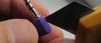
The wiring of conductors on a double-sided printed circuit board is made using the LUT method (laser ironing technology).
Manufacturing a board using laser-iron technology
LUT is the process of transferring the drawn wiring of a printed circuit board onto foil material . This procedure consists of the following:
- Using one of the existing programs for creating printed circuit boards, the layout of the future element is carried out on the computer screen;
- using a laser printer, print the resulting design onto a sheet of glossy paper;
- apply a sheet of paper with an image of a printed circuit board to the preheated foil material;
- use a hot iron to iron the paper with the printed circuit board image, thus transferring the design to the surface of the foil;
- After ironing is completed, the foil material is placed in a bath of warm water and the paper is carefully removed so as not to damage the toner applied to it.
Attention! The image of the printed circuit board on the foil material will be a mirror image of the pattern obtained on the computer screen.
The board is etched in a bath of ferric chloride solution. At the end of this procedure, the resulting board is thoroughly washed. Then all the necessary holes are drilled in it. And then, using flux with a small amount of tin solder, they tin the side where the radioelements will be soldered.
Next, all radio elements are installed on the printed circuit board, starting with the power supply circuits. Considering that the amplifier's electrical circuit consumes about 150 mA for each power supply arm, the output transistors need to be installed on a radiator using mica spacers and thermal conductive paste.
Advice! To obtain high sound quality, it is important to select transistors with the same transmission coefficient, ensure that the spread of the nominal values of all resistors does not exceed 1%, and purchase a high-quality volume control.
You need to know that headphone amplifiers with fairly high technical characteristics can be assembled on the basis of widely used microcircuits LM358N, TDA7050, K157UD1 or their analogues. All of them have a minimum coefficient of nonlinear distortion and a low level of intrinsic noise.
The third version of a headphone amplifier, cool
This circuit is a slightly reworked version of an amplifier from the “almost Hi-End” category (don’t let fans of tubes wince - there are also transistor circuits of this class). The scheme was published in the magazine “Radiohobby”, No. 6, 2003, author - Vyacheslav Shchutsky.
In its original form, it was a class “A” amplifier with an output power of 25 Watts into a 4 Ohm load, a power dissipation of 60 Watts and a quiescent current of the output transistors of 2 Amps (!).
This is a complete unit that is an input voltage repeater with a voltage gain slightly less than unity. It had to work with a high quality voltage amplifier. (The sound card will fully provide this amplifier with the required signal level; it only needs to be amplified in power.)
The load (in the original) should be highly sensitive acoustic systems, for example, monitor type. In this case, this “heater” will be used as a headphone amplifier.
Naturally, the quiescent current can be made smaller (for this you will have to change the resistance value of some resistors), and replace the output transistors with KT854A (we had to leave the KT819 transistors in the circuit - there were no others available). The capacitors, oh, were installed during revision. The values in parentheses refer to the “original” amplifier circuit (if you need to get 25 Watts at the output).
In this circuit it is clear that the amplifier does not have feedback, which, according to many experts, makes it difficult to feel the difference between the circuits. But at the same time, the requirements for the quality of each element of the circuit increase, which will be discussed later. Let's look specifically at the features of this development.
The input stage of the amplifier is made according to a circuit with a common collector (CC) on transistor VT1 with an active load in the emitter circuit in the form of a stable current source (IST) on transistors VT2, VT3. Transistors VT2, VT3 are installed on a common heat sink with an area of 30...40 cm2.
This circuit design makes it possible to install transistors on a common heat sink and ensures high stability of the IST current and the quiescent current of the output transistors. The collector current of the input transistor flows into the base of the transistor VT5, on which the IST for the output amplifier transistor VT4 (Push-Pull principle) is built.
The output amplifier transistor VT4 is also connected according to a “common collector” circuit, and the entire amplifier is assembled according to the “OK-OK” circuit. Transistors VT4, VT5 in the original version were installed on a common heat sink with an area of about 800 cm2.
To drive the headphones, you need very little power, so we’ll set the quiescent current lower, the power dissipation will be reduced and, therefore, there will be no need for a “monstrous” radiator. In the manufacture of the “ear” amplifier, a relatively small radiator from P-II was used, on which all five transistors were installed through insulating gaskets made of thermal film or mica (first strengthen the transistors, check with an ohmmeter for absence of short circuits to the radiator, and only then solder!).
Naturally, you will need two such radiators - one for each channel. The fans can be removed, but if it turns out that the heating of the radiators is too high (more than 80°C), you will have to return them to their place (maybe you can reduce the quiescent current?).
Setting up the amplifier is done as follows. Before turning on, the correct installation is checked, the trimmer resistor slider is set to the middle position. After switching on, it is necessary to check the potential at the emitter of VT4 (half the supply voltage).
If the voltage is different from 6 Volts, adjust the trimming resistor. After setting it up, you can replace it with fixed resistors, you can guess how exactly. In the manufactured sample, the quiescent current of the first channel is 120 mA, the quiescent current of the second channel is 240 mA. Despite such a noticeable difference (the transistors are to blame - I had to install KT814 with different letter indices, hence the scatter), it was not possible to detect any differences in sound quality (probably because the headphones are not too expensive or the ears are deaf). But it is still better to select transistors in the channels so that the quiescent currents are approximately equal.
If the quiescent current is insufficient, the resistance value of resistor R5 should be reduced. If necessary, you can additionally adjust the voltage at the VT4 emitter by visually monitoring the uniformity of the limitation of the sinusoid with a frequency of 400...1000 Hz (top and bottom) on the oscilloscope screen with a connected load. During setup, a resistor with a resistance of, for example, 33 Ohms can act as a load (we choose it approximately equal to the resistance of the headphone winding).
Now - about the details of the rectifier. Its diagram is not given because it is a standard bridge. It is better to use rectifier diodes with a large crystal area, for example KD213. The capacity of the electrolytic capacitors in the rectifier is based on the principle “the more, the better” (in the manufactured sample, two 4700 μF capacitors with a maximum voltage of 25 Volts are installed “in parallel”). The voltage at the rectifier output must be at least 15 Volts.
But it will not be possible to power the amplifier from a simple bridge rectifier. The fact is that amplifiers of this type are very sensitive to supply voltage ripples. You will need to make a small 12 Volt voltage stabilizer. For this purpose, a suitable microcircuit is a voltage stabilizer 7806, connected according to the circuit shown in the figure.
The zener diode helps increase the output voltage of the stabilizer to the required 12 Volts (or rather, there will be 6 + 5.6 = 11.6 Volts, but these are minor things). The current consumption is small, so the radiator for the stabilizer chip can be used small in size.
To reduce the influence of stereo amplifier channels on each other, companies use tricks of varying degrees of “steepness” - for example, completely separate block designs (two “monoblocks”), power from different transformers, power from separate windings of one transformer, power from different rectifiers connected to one winding of the transformer. Choose for yourself which option suits you best. Another recommendation is to place capacitors of another type, for example MBGO or MBGCH, in parallel with the electrolytic capacitors in the power supply circuit - this improves the sound of the amplifier at higher frequencies of the audio range. You can select the capacitance value of such capacitors yourself, based on your hearing.
The recommended type of capacitor C1 is the so-called “paper-oil” (at least MBM), the output electrolytic capacitor is type K50-29V or imported (Elina for Audio, Marcon). But you can also install more affordable ones, if you check and select the best ones according to the parameters. It is also possible to connect smaller capacitors in parallel. For example, instead of a 2200 uF output capacitor, two 1000 uF capacitors had to be connected in parallel (). MLT type resistors with power dissipation 0.25…0.5 W.
It is believed that the larger the element, the less noise it creates. I suggest you check it out for yourself.
The printed circuit board for this amplifier was not developed; all installation was performed with a single-core insulated wire. If you wish, you can perform the entire installation with silver-plated copper wire (then you will proudly show off your amplifier to your friends - just make the case in a modder style, with a transparent window and LED backlighting).
The case for this experimental sample of a headphone amplifier was made of foil fiberglass, with radiators for channel amplifiers mounted on the side covers. True, the design turned out to be something vaguely reminiscent of the English tank “Big Willie” from the First World War. The LED power indicator, headphone jacks and parallel amplifier jack are located on the front panel.
The frequency response of the amplifier is linear, the range of reproduced frequencies is from 20 Hz to 120 kHz (the generator’s capabilities were not sufficient beyond that). There was no need to adjust the timbre while listening to music.
The magnitude of nonlinear distortions could not be measured due to the lack of necessary instruments. But we can hope that the distortion will be very small - after all, the transistors operate in class “A” mode. It is impossible to detect any noise when the amplifier is turned on - there is complete silence in the headphones during pauses. What you need to get...
And I also liked playing - during the explosions of grenades and shells, there were no creaks or overtones in the headphones - only what the developers wanted to “voice”.
A headphone amplifier can be used for comparative testing of stereo headphones, and playing is also not forbidden. But it is recommended to listen to high-quality music, otherwise all the shortcomings (sound card noise, wheezing of headphones, interference from drives, etc.) will show themselves very clearly.
Of course, it was possible to conduct comparative studies on the topic “The difference in the sound quality of stereo phones when they are connected directly to the output of a sound card and a specialized amplifier” with the involvement of a crowd of experts and piles of measuring instruments, but then the entire volume of the article would have to be devoted only to this topic.
Maybe it seemed to you that there was no need to sculpt such a bulky box for playback only through headphones? Then why do people pay such ridiculous amounts of money (go to www.hi-fi.ru and look at the prices) for amplifiers, speakers, and even connecting cables?
Yes, of course, this device will be inferior in characteristics to amplifiers assembled on tubes and transformers wound with silver wire (Audio Note, etc.) But still, compared to the work of Chinese assemblers, the sound of this homemade product is completely different - I checked it personally.
Radio amateur
Competition for beginner radio amateurs “My amateur radio design”
DIY circuit of a simple high-quality headphone amplifier on a chip
Competition design for a beginner radio amateur “High-quality headphone amplifier on the TDA2003 chip”
Hello dear friends and site guests! I present to your attention the fifth competition entry of a novice radio amateur. Author of the design: Morozas Igor Anatolyevich :
Hello radio amateurs!
I suggest you look at my second design - this is a high-quality headphone amplifier based on the TDA2003 chip .
The amplifier circuit was taken from the Internet. There is a whole forum based on this scheme. Most radio amateurs responded positively to it. A radio amateur from Europe even made measurements that confirm that the amplifier operates in class A. Gain = 18. This power seems to me to be more than enough for any music lover. So I decided to check it out for myself.
Here is the basic diagram of one channel with a power supply:
Here is a word-for-word translation of the text about this amplifier from a European radio amateur:
“This very simple circuit is based on the TDA 2003 chip, and gives excellent performance equal to the very best commercial designs costing hundreds of pounds. The manufacturer's data sheet for the TDA2003 gives a distortion figure of 0.15% at a 4.5 W output, and a voltage gain of 100, but in this application the voltage gain has been reduced to 18 by increasing the overall power-back ratio, and the output power is reduced by approximately 10 mW. As a result, the harmonic distortion coefficient is reduced to 0.006%, a very low figure indeed. The gain was set at this level to suit my Sennheiser HD25SP headphones, with the amplifier driven beyond its nominal 200 mV source. The 10k pot magazine can be used as a volume control if necessary. The power supply can be increased to 18v, allowing higher output power at the same level of distortion. This may be appropriate if less sensitive headphones are used. Please note that to avoid instability problems, a strict one-point grounding circuit must be used. The common ground point should be as close to pin 3 as possible.
The spectrum shows noise and distortion relative to the 1Vpk output at 1 kHz, which is a very loud signal in the Sennheisers. The second harmonic is at -90dB and the 3rd harmonic is below -88dB. This corresponds to a total harmonic distortion figure of 0.006%. The noise is shown as below -100 dB level, but with a hum spike at -84 dB. The transient response at 1 kHz square wave is also shown in the figure. There's no sign of ringing, overshoot or any transient distortion beyond what appears from the amplifier's final band. The passband has 3dB points at 10 Hz and 50 kHz. All performance characteristics were measured with the headphones included:
Objectively, the use of this amp is flawless, and it also sounds as sweet as one would expect. It starts up quietly, and won't stun you or blow up your expensive phones with a lot of charging transient. In short, highly recommended, especially if, like me, you feel that the performance goal is a good starting point for an audiophile evaluation of a product. Spectrum analyzer software Spectrum Laboratory Wolfgang Buescher (DL4YHF)."
As always, the most “difficult” part when assembling a radio circuit is to fit everything into the housing. Therefore, I first purchased a case from a radio store, and after internal measurements of this case, I laid out a printed circuit board for it in the Sprint-Layout 6.0 program. I made a few changes to my version. Firstly: I added a double variable resistor to the input, instead of the electrical capacitor C1 I installed a Wima 2.2 µF film capacitor and increased the electrical capacity in the power supply. capacitors up to 6800 uF.
The board was manufactured using LUT technology. There is a lot of information about this technology on the Internet. I print tracks on 130g thin glossy photo paper. I set the power of the iron to the third level and heat the board with photo paper for no more than 30-40 seconds.
After etching the board in ferric chloride and cleaning the copper tracks with acetone from the cartridge paint, I tin the tracks in ROSE alloy. I throw a few drops of the alloy into a suitable container with water. As soon as they melt, I place the board with the tracks facing down and begin to move it along the bottom of the container. Then I turn it over and use a sponge to wipe off all the excess buildup on the paths. When tinning in this way, pay special attention to the issue of ventilation. Vapors from ROSE alloy are poisonous!
I like it when everything looks factory, so I made LUT from the parts side too:
Assembling amplifier parts onto the board:
Installing the amplifier board into the case:
I made the front panel this way. In the Photoshop program, I drew the appearance of the front panel where a variable resistor, input and output sockets and an LED should be installed. The finished drawing was printed with an inkjet printer on thin glossy photo paper. On a prepared, fat-free panel with holes, I glue photo paper with wood glue and place the panel under the so-called press. For a day. As a press, I have a 15 kg barbell plate.
A printed drawing on photo paper is pasted onto the front panel:
A day after the glue has dried, I laminate the surface with thermal film so that the design on them does not wear off over time. I do this with a regular iron through paper:
And here is the final result of the build:
Well, now about the sound. If you do not take into account that this is my first amplifier and I have never listened to “cool” headphone amplifiers before, I was very pleased with the sound. The sound is clear, if you listen to a good quality recording, the sound is even crystal clear. All instruments are auditioned. There is bass, but it is dense without rattling. It seemed to me that there were too many high frequencies. The volume is so loud that you can actually go deaf. In order to more clearly evaluate the sound of this amplifier, I decided to build another headphone amplifier using the OPA2134 chip
Attachments to the article:
Headphone amplifier circuit in .spl7 format (32.6 KiB, 3,857 hits)
Headphone amplifier circuit board in ,lay6 format (113.6 KiB, 4,428 hits)
Front panel in “Front Designer” format (39.6 KiB, 3,050 hits)
Dear friends and site guests!
Don’t forget to express your opinion on the competition entries and take part in voting for your favorite design on the site’s forum. Thank you.
Go to the forum
Fourth headphone amplifier circuit, for those “moved” to the tube side
This headphone amplifier circuit (author - B. Kainka, Elektor Electronics magazine, No. 10/2003, p. 70) uses a lamp that was used in radio stations that were once in service with the Soviet Army (R-105M, R- 108M, R-109M and others). And in DOSAAF, such radio stations were used for a very long time - for example, the R-108M was suitable for operating in the 28 MHz range.
Lamp 1P24B - direct filament pentode, rod type, small-sized. The filament voltage indicated in the diagram is 1.2 Volts at a current of 240 mA.
The anode voltage here is low - only 12 Volts, so you don’t have to worry about hundreds of volts coming from the anode circuit.
Headphones are connected directly to the anode circuit, the winding resistance of which must be at least 600 Ohms (they say that there are such “ears” from the “studio” category). And of course, you will need two such lamps - after all, we are supposed to have “stereo”...
The power supply circuit is not given specifically - if you are going to solder this circuit and have found such lamps that are not very common on the market, then in the future you will definitely not need my help in this particular area.