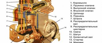
Translation of an article from the blog of Indian engineer Amaldev V.
This project had been brewing in my head for about two years, and I still couldn’t get around to it. There is nothing complicated or overly technological in the project. Anyone who knows how to make anything with their hands should be able to handle it without any problems. I've made the entire project freely available, and you should be able to order all the parts and assemble your device for less than $10.
Background
I currently live in Mumbai, in an apartment overlooking a very busy road.
And since I moved here, I have been struggling with the dust that settles on everything whenever I open the windows. Weekly cleaning of the apartment takes a lot of effort. And I decided to buy an air purifier for the room. And then I thought: how difficult would it be to assemble the purifier yourself? I did some research and decided that I needed to make myself an ionizer (by the way, an ionizer and a purifier are two different devices, but more on that later). However, then I got buried in current problems and never assembled it. https://www.instagram.com/p/B6pRxfXJ_jU/ But lately many people have asked me how I design and make devices, and I decided to give this relatively simple project as an example and describe its creation in detail in the form of instructions
So let's make an ionizer.
Research
If you want to do something yourself, do some research using Google first.
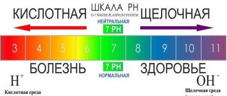
In our case, let's figure out what an ionizer is and what basic principle it works on. An air ionizer (or negative ion generator, or Chizhevsky chandelier) is a device that uses high voltage to ionize (electrically charge) air molecules. Negative ions, or anions, are particles that have one or more extra electrons, causing their overall charge to be negative.
So far it seems simple. Ionizers are used to remove particles from the air by giving them a negative charge, after which these particles are attracted to a positively charged surface (wall/floor). As a result, the particles settle much faster, leaving the air cleaner. This is exactly what we need - to remove dust from the air so as not to inhale it.
So after just 5 minutes of searching, we already know that we need to make a high voltage system that gives a negative charge to the particles. This was a little disconcerting at first because I had never made a high voltage system before and if you play with such systems carelessly it can end badly.
Then we go and look for devices already on the market that use this technology. I do this in order to understand what kind of circuits people used to create such devices. If there is a device on the market with the same technology, learn from it.
People spent a lot of engineering man-hours creating the device. Learn from their example to make your own system that is at least similar to the finished one, or learn from others' mistakes and make a better system.
For similar purposes, Google is also your best bet. I found some evidence that ionizers were being done back in the 1980s. If this technology is that old, I might look at a description of how these devices are disassembled. We search Google for “ioniser teardown” and find a bunch of videos showing the insides of the device. I recommend very good videos by BigClive.
Based on these videos, I realized that a high voltage system can be made using a voltage multiplier, and that it is not that difficult. So let's move on to electronics design.
Car ionizer
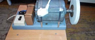
Cars are enclosed spaces just like regular rooms. The difference between them is that in addition to microscopic dust collecting inside the cabin, the negative impact of existing electrical devices, an increased degree of influence of gasoline and oil emissions is added to the list of harmful factors. Under such conditions, an ionizing device is certainly necessary. You can buy it, or you can, again, assemble it yourself.
First of all, you should understand the operating principle of such a device: it is connected to a voltage converter. The converter circuit is the simplest for all those who have at least a little knowledge of technology. The active element in it is a transistor. It is best to use transistors of the KT 818 or KT 819 series; in this case, practically nothing will have to be changed in the circuit. We use KTs106 diodes and analogues as a voltage multiplier.
When choosing a capacitor, pay attention to its operating voltage, which should be in the range from 3 to 6 kV, and to the capacitance - 600-4500 μF.
The winding of the finished transformer should be done in layers, each of which should consist of 100 turns. Each layer is subject to very careful insulation. After these manipulations, it is advisable to fill the transformer with epoxy resin. We wait for the resin to dry, connect the timer, connect it to a voltage multiplier, spread the output wires to 3 cm and connect it to the network.
Electronics design
We need a voltage multiplier.
First, learn everything you can from the free content. Never do anything without first learning everything you can for free. It is very important. You need to take the time to research, or you'll keep making the same mistakes. I spent a couple of hours studying the design of voltage multipliers. The simplest solution, the Cockroft-Walton generator, is most often used.
One of the principles I try to adhere to when developing complex solutions is Keep IT Simple, Stupid. Or just KISS.
Therefore, the Cockcroft-Walton generator was suitable for me. It was developed in 1932, and since then it has been used in hundreds of devices. Therefore, this is a fairly reliable option for implementation. After some more googling, I found a video by Dave Jones explaining how this circuit works. I recommend watching the video to understand this better.
Essentially, the circuit consists of two diodes and two capacitors connected back to back. The input is supplied with alternating current with peak voltage Vp. The first part of the circuit shifts the input signal so that the output is a constant current with a peak voltage of 2Vp. By adding one more stage, we get 4Vp. You would think that the next stage would increase this value to 8Vp, but no - only to 6Vp.
By adding stages, we increase the output voltage. 2Vp, 4Vp, 6Vp, 8Vp, 10 Vp, 12Vp, and so on, relative to the input. At least in theory - in practice there will be losses in the circuit and the output will not be as large, but for our purposes it does not need to be extremely accurate.
Returning to our system: we want to output high voltage direct current (about 6-7 kV). To simplify the circuit, I decided to supply it with 230 V AC directly (this is the voltage in the Indian power grid) [as in the Russian / approx. transl.]. Suppose we make a multiplier with 15 steps, then the output will be DC voltage 230V x 2 x 15 = 6900 V (theoretically). Sufficient for ionization.
I could have added a transformer to the input and increased the output voltage more with fewer steps, but for the first prototype I wanted to keep it very simple. Therefore, we will leave 15 steps and an input voltage of 230 V.
Next we need to select the components. The circuit is very simple - two capacitors and two diodes per stage. How do we select their values and rated power?
And this is where a correct understanding of the operating principle of the circuit will come in handy. You can see that at each stage the voltage on the diodes or capacitor does not exceed 2Vp. The potential difference is always 2Vp, so we don’t need to spend money on high-voltage diodes and capacitors. Since the input is 230V, any capacitor rated at 500V or higher will suffice. Its capacitance is not important, so I chose a 0.1 µF capacitor and 630 V. I chose surface mount because I am used to soldering such components. I chose 1N4007 diodes for 1000 V. The main thing is ready. A list of materials is available.
DIY air ozonizer
Recently, devices called “Ozone Generator”, simply called “Ozonizer”, have become extremely popular; they are used for ozonizing water, air, food, destroying microbes, bacteria, microorganisms dangerous to human life and harmful flying, running, crawling insects. There are a huge number of ozonizers on sale; the price of devices fluctuates in wide ranges, sometimes reaching cosmic values. Therefore, dear friends, I suggest you make a simple air ozonizer with your own hands, from available parts. This figure shows a simple diagram of an air ozonizer; even a schoolchild can assemble it.
The circuit consists of a rectangular pulse generator assembled on an NE555 timer chip. The principle of operation of the device is simple, the generator produces rectangular pulses with a frequency of 1 kHz and a duty cycle of 50%. For those who are not in the know, I’ll explain: Duty factor is a dimensionless quantity, it is a classification feature of a pulse system, it determines the ratio of the pulse repetition period to the pulse duration. Next, from the third leg of the microcircuit, the pulse arrives through the limiting resistor R1 to the base of the amplifying transistor T1, which opens and passes current through the winding of the line transformer (TDKS).
The voltage at the transformer output increases to 25-30 kV depending on the TDKS model. High voltage is applied to the spark gap and a corona discharge occurs, resulting in the production of ozone gas. I would like to draw your attention to the fact that in this device a corona discharge will occur only at a frequency of 1 kHz. If you raise the frequency to more than 2-5 kHz, you will get a burning electric arc during the combustion process and a large amount of heat will be released. Don't confuse these two things. To assemble the ozone generator you will need the following parts:
Radio components for assembling an ozone generator
- Chip NE555 or analogue KR1006VI1
- DIP panel for SCS-8 chip (DS1009 - 8AN)
- Transistor T1 MJE13007, MJE13009, KT805, KT819 and other npn structures designed for a current of at least 5A
- Linear voltage regulator L7809CV
- Non-polar capacitors C1 10 nF (103), C2 1 µF (105)
- Resistors 0.25 watt R1 100 ohm, R2 1K, R3 71K
- TDKS almost any from an imported color TV
- A radiator, for example, from a computer power supply
- Metal pipe with a diameter of 25 mm, length 120 mm
All parts are located on a small printed circuit board measuring 22x28 mm. I also allow you to assemble the ozone generator using wall-mounted installation.
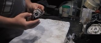
The main part of the ozonizer is a line transformer; you can get it from any imported TV. Why imported? Because imported TDKS have a built-in diode voltage multiplier. The model of the transformer and TV does not matter. All TDKS have the same three pins needed for our homemade product, the only difference on some lines may be one, two or three armored wires and the absence of unused pins. Thin wires can be cut off, leaving only the thickest, central, armored wire.
The transistor will get very hot, so it should be mounted on a radiator with sufficient area for normal cooling. The end of the armored wire coming out of the line transformer must be cleared of insulation and the metal veins slightly fluffed up, giving the shape of a brush. Before starting the ozonizer, place the end of the armored wire about a centimeter from the edge of the pipe.
A device correctly assembled from serviceable parts begins to work immediately and does not require configuration. After power is supplied to the generator, a blue glow will appear between the wire and the pipe emanating from each vein of the armored wire; this is the same corona discharge accompanied by a loud hissing and the release of a large amount of corrosive ozone gas. The device consumes only 0.8A.
PCB design
Having selected the important components, let's choose the rest.
We need to plug the device into an outlet, so we need a resistor at the output with a value large enough to prevent anything from happening (for example, so that if you accidentally touch the circuit, current will not flow through you). I would also like to reduce the current to a minimum so that the device consumes as little power as possible when turned on. I chose two 10MΩ resistors (0.25W, 1% tolerance, 1026 case) and this will give us currents measured in microamps. I chose LCSC.com to purchase components. It's cheaper there than Digikey or Mouser. Searching the parameters gave me the resistor 1206W4F1005T5E.
I would also like to install an LED indicator that lights up when the device is turned on. The current passing through it must be very small. I have used this LED in other projects and it lights up quite well at 2mA. To limit the current, I took two 51 kOhm resistors (230 V / 2 mA gives 115 kOhm). The two resistors dissipate more heat (P=I2R: (2 mA)2 x 51 kOhm = 0.2 W). Therefore, I chose two resistors of 51 kOhm and 0.5 W. On LCSC it is CR1210J51K0P05Z.
Now we need to understand what the output will be. From the analysis of ready-made ionizers, it follows that in order to transfer negative ions to dust particles we need something sharp. I decided to use sewing needles and solder them to a large pad at the outlet. I chose a set of needles from the local market for 30 rupees ($0.4). In principle, any conductive material with sharp ends will do. Carbon fiber with sharp tips will work best. The more sharp tips, the greater the ionization.
Taking all this into account, let's design the board. For this project I am using Eagle. I came up with the following diagram:
It has two AC input pads, 15 multiplier stages, current reduction resistors, a large output pad, and LED circuitry. I recommend that you always write down the part numbers you use to make it easier to find and order them in the future. All components cost me $7.8, and most of that went to capacitors.
I decided to make this diagram elongated. To mount the board, I placed holes in the corners and used M3 screw holes. The dimensions of the board are 145 x 40 mm, there is an entrance on the left, and a large area for soldering sharp needles on the right. Make sure that the diode placement directions are marked, this will make assembling the device much easier.
Now you need to draw the board in Gerber format and send it to the manufacturer. I am collaborating with JLCPCB for these purposes. The cost of prototype boards is very low. The fee will cost you $0.8 (not including shipping) when purchasing 10 pieces.
If you want to remove my name, date and board title from the files, please edit the Eagle Board files. Here's what the final board will look like:
You can import it into Fusion 360 and get this beauty:
I combined ordering the board from JLCPCB and components from LCSC. When ordering together there is a $15 shipping discount. The cost of the board and components is approximately $9 (not including shipping). Everything arrived in a week and a half. JLC has a board assembly service, but I like to do everything myself.
Assembly and testing
This is what the JLCPCB board turned out to be like. I chose the ENIG-RoHS finish because it's nicer. But the HASL finish will be cheaper.
Soldering all the SMD components took me about an hour. At a local store I bought 2 meters of wire and a plug to connect to the outlet. I tied a knot in the wire so that the wire would not come out of the plug.
The next step is optional, but I highly recommend it. I turned to a company that has laser cutting, took with me a piece of plexiglass 3 mm thick, and cut out a protective cover from it. I recommend making one - when I tested the board, I was shocked a couple of times when I accidentally touched the capacitors. The DXF file for cutting is also included along with all the files.
I screwed the cover to the board using 5mm long M3 plastic screws and made 20mm long plastic legs.
I soldered seven pins to the output pad. The bigger, the better. The difference in length doesn't matter.
It's time to plug the device into a power outlet and test it. The LED should light up and ideally the device should work.
You can quickly check the functionality by bringing your wet palms to the needles (just don’t touch them!). You will feel the movement of cold air coming from the needles. This is ionization. Negative ions are repelled and constantly fly away from the tips of the needles.
To prove that the device could cause smoke and dust particles to precipitate, I prepared a transparent jug, filled it with smoke, and stuck the device into it with the needles inside. After turning on the device, the smoke particles settled very quickly.
https://www.instagram.com/p/B6pRxfXJ_jU/
In the video, the smoke appears to be dissipated by air blowing in the jug. In fact, there is no draft there - the jug is closed. The effect occurs due to the repulsion of negative ions, and air very quickly begins to circulate throughout the jug.
After making sure that the device was working, I plugged it into the outlet and left it running. It should disperse dust around itself without any problems. Ideally, install it next to a window where there is a draft, so that the device ionizes all the dust passing by. I plan to set it up like this and leave it on.
What about power consumption? It is very small. The LED consumes the most. It takes about 2 mA. Over the course of a year, the device must generate 230 V x 2 mA x 24 h 365 d = 4 kWh. For us it will cost 4 rupees ($0.05) per year. To save even more, you can simply remove the LED from the circuit, then the energy consumption will be 1000 times less, and it is unlikely to be noticeable on the meter at all.
This is how we assembled an ionizer for just $10. I hope it helps reduce the amount of dust that settles in your lungs.
After it's been running for a couple of weeks, you'll notice dust starting to accumulate around it. This is fine. It's better for it to sit there than for you to inhale it.
For the US and countries where the voltage is 110V, the output voltage will be lower (theoretically about 3kV), but the ionizer should still work.
What else can be improved in the device: replace the needles with conductive carbon fiber brushes. The more sharp ends the device has, the better the ionization. If you distribute the tips over a large area, the chances of ionizing a larger volume of air increase.
What is required for assembly?
The list of necessary products and materials will depend on the type of homemade ionizer. Let's start with the simplest design. To make such a device we will need:
- a pair of plastic boxes of two halves that are inside each Kinder Surprise;
- a pair of wires with a diameter of 0.5 mm;
- removable plug;
- insulating tape;
- scissors;
- needle.
Having tried your hand at making a basic ionizer, you can move on to a more complex version designed for use in a car. To create such a device you will need the following components:
- transformer;
- converter generator.
The type of generator does not matter; even a single-contact one will do.
If you find the once-common 555 integral timer among the old junk in your garage or closet, you can remove the generator from it. It has a primitive design, but is quite suitable for a homemade ionizer.
Afterword
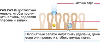
After this article was published, some people became concerned that the device could also generate ozone.
However, the operating scheme of the ozone generator is slightly different (although the principle of corona discharge remains the same). In the couple of weeks that I've had this device running, it doesn't seem to generate any ozone (or so little of it that I don't feel it). Also regarding the difference between ionizers and air purifiers. The ionizer cannot serve as a replacement for HEPA filters installed in purifiers. Ionizers only help to remove dust from the air. These particles remain on the floor. It does not trap smoke particles like a filter purifier does.
The benefits and harms of devices
An air ionizer is needed to clean the air from dust and bacteria. A device that produces ions can have both a positive and negative effect on the body. Of course, there are more beneficial effects: your well-being improves, your immune system strengthens, fatigue goes away, general tension disappears, and your mood improves. Ionization is especially useful for people with asthma and bronchitis, as the flow of oxygen to tissues increases. However, while cleaning the room from bacteria and spores, unpleasant odors and dust, the device creates additional troubles for people.
We recommend that you read: Instructions for dismantling the air conditioner yourself
After treating your home with an ionizer, you should do a thorough wet cleaning to remove dust and various harmful particles and microbes that have settled on furniture and walls. If you have pets in the house, it is advisable to purchase an ionizer equipped with an ion counter. Expectant mothers need to be careful when using an air ionization device.
It can bring benefits and harm to the well-being of a pregnant woman, depending on the device chosen, since each of them may have its own contraindications.
Before purchasing, you should definitely consult a doctor so as not to harm yourself and your unborn baby. For small children, ionized air is also useful, but they should not be in the room during the procedure, and after two hours the room needs to be wet cleaned. As for newborn children, a salt lamp that does not emit ozone is best suited for them. The room is cleansed and filled with ions naturally. The child sleeps better and the body becomes healthier.
You need to know that with frequent use of the ionizer in the room, static electricity accumulates, so the presence of a meter on the device is mandatory. The ionizer cannot be used for cancer patients. This is due to the fact that air ions promote metabolism, improve the nutrition of cells, including diseased tissues, which leads to their growth. Ionization is also harmful after surgery and during various inflammations in the body. Air saturated with ions is also undesirable for patients with nervous disorders, as well as joint diseases.
Safety
If you decide to build such a device, be careful.
Take precautions when working with high voltage AC input and high voltage DC output. Do not give the device to children. Make sure the AC cables are well soldered and that there are no exposed wires outside the board.
Use a plastic cover, do not touch the circuit components when it is turned on. Discharge capacitors by shorting them with a conductor with an insulated handle,
Make a knot in the power wire where it meets the board so that no one can rip it out of the board.