Refrigerator start relay connection diagram
This part is needed to start an asynchronous single-phase compressor motor. There are no difficulties in connecting the relay. The starting and operating windings are connected to the motor stator. The first is involved in starting and starting the compressor, the second keeps the rotor in working condition and continuously supplies alternating current. There is a start-up relay that regulates the supply and turns off the power to the working and starting windings.
Inductive short circuit
Power is supplied to the input of the device: “zero” and “phase”, at the output the latter is divided into 2 lines. One is connected to the starting winding through the starting contact, the other is connected to the working winding of the motor. In the relay, current is supplied to the working winding through a spring, the resistance of which is quite high, then through a connection with a bimetallic jumper. This element has the property of bending in one direction under the influence of elevated temperature. As soon as the current in the circuit increases significantly, for example, if a short circuit occurs between the turns or the motor jams, the spring that comes into contact with the jumper heats up. The latter changes shape, after which the contact opens and the compressor turns off.
In order to start the motor in this circuit, a coil is used, connected in series with the working winding. When the rotor is stationary, voltage is applied, which causes an increase in the current in the coil. A magnetic field is formed, it attracts the movable core, which in turn closes the starting contact. After the rotor picks up speed, the current in the network decreases and the magnetic field decreases. The starting contact is opened by a compensating spring or gravity.
Posistor switching
The starter consists of a capacitor and a posistor, which is a type of thermal resistor. In the compressor circuit, the capacitor is installed between the buses of the starting and working windings. This mechanism provides the phase shift necessary for the compressor motor to turn on. The posistor is connected in series with the starting winding. When starting, its resistance is insignificant; at this moment a large current flows through the winding. When it passes, the posistor heats up and its resistance increases greatly. Because of this, the auxiliary winding is almost completely blocked. The part cools down after the voltage supply to the compressor stops.
Operating principle of the refrigerator start relay
The control type mechanism, which controls the operation of the cooling equipment, is small in size and located in close proximity to the compressor. There are two types of relays:
- launchers;
- Start-protective.
The latter variety comes in two types:
- Current . It turns on when the electric current reaches a certain value. The motor consumes this electricity, and if it overheats, the relay cuts off the power. When the motor cools down to a certain temperature, the trigger turns it on again.
- Current-thermal . The starting relay is triggered by thermal indicators and electric current values. A running motor consumes electricity passing through the coil, which heats up slightly without affecting the biometric plate.
Starting relays come in several types, but there are two main functions:
- starting the starting winding;
- stopping the supply of electric current at increased engine speed.
Based on the principle of operation, devices are distinguished:
- tablet (posistor);
- induction
A posistor, a type of thermal resistor, together with a capacitor located between the buses of the working and starting windings, are the main parts of the tablet. The last part of the design provides a phase shift that turns on the refrigerator compressor motor.
The maximum electric current flows through the winding, heating the posistor and increasing its resistance. Electricity keeps a type of thermal resistor warm while the compressor is running.
The tablets include:
- RT;
- RCT;
- P3R;
- RP3P2;
- 6SP;
- A.E.G.
The main working part of the induction relay is a solenoid, the coil of which is connected to the working winding of the compressor motor. Electric current at its maximum value passes through the coil, creating a strong magnetic field. The attractive force of the latter attracts the current-conducting contact, completing the circuit.
A set of required rotor speeds becomes a signal to reduce the current strength, which reduces the impact of the magnetic field. This allows the core to restore its original position by opening the contacts. A prerequisite for the operation of the induction relay is a strictly horizontal location of the part inside the refrigerator.
Operating principle of refrigerator start-up relays
In order for an installation intended for storing food to operate properly and uninterruptedly, its technical condition should be carefully monitored.
It is much easier to do this if you know the operating principle of the most important components of the unit. The starting relay of the refrigerator, called a “switch” in everyday life, is responsible for the timely switching on of the starting winding during equipment startup, and also interrupts the current supply if the motor begins to rotate at a frequency of 75% of the maximum. A small part performs a number of important functions, so any malfunction can cause serious damage to the unit. The operating principle of the refrigerator start-up relay is quite simple; it is based on the properties of a bimetallic plate that changes shape when heated. The latter is heated by contact with a current-conducting coil. If the motor consumes a small amount of current, the spiral heats up slightly and does not affect the bimetallic plate. When the amount of current consumed increases, the heated spiral transfers heat to the plate, which in turn disconnects the contacts in the compressor power circuit. You can check the condition of the refrigerator starting relay using a tester - if the resistance between the contacts is zero, the device is working properly. If the circuit is broken, the “switch” should be replaced.
Operating principle of the starting protection relay
The starting coil must be turned off when the speed is up. At the moment of start, the windings consume a large current, the effect allows you to track the moment of recommutation. The refrigerator start relay performs protective functions (not always). The option is implemented by heating the sensitive element with electric current. The threshold is exceeded - the circuit breaks, regardless of whether the desired refrigerator mode has been reached according to the thermostat readings or not. Two schemes for the operation of the starting relay have been invented (at the same time it can be protective):
- "Tablets" work on the basis of a material that expands by heat. Initially, the working element is cold, the starting winding consumes current, ensuring a smooth start of the asynchronous motor. Gradually, the temperature of the tablet rises, causing the contact to open, and the working coil remains switched on. We believe that to maintain the mode, a mechanism is installed inside the relay to prevent the tablet from cooling. Operating winding choke, heating element. If a button relay breaks, you can often hear the rustle of scattered powder inside, changing the position of the device body.
- Induction relays are based on the action of electromagnets. When starting, the current is high and due to this the core presses the contacts of the starting coil. Over time, engine consumption drops. As a result, the current will no longer balance the spring, and the contacts of the starting coil open. Please note: it is important to orient the relay in space correctly. Often the core falls, carried away by the force of gravity. But testing such elements is much simpler: turn from side to side so that the contacts of the starting relay change the resistance from zero to infinity.
The tablets often come with thermal relays on a bimetallic plate in the same housing. The current of the working coil passes through it. As soon as the value exceeds the response threshold, the contacts open, stopping the compressor. The bimetallic type refrigerator relay circuit is based on heating the sensitive element. There is nothing complicated about it! The two plates are welded tightly to each other. The coefficient of expansion of metals in them is different. When heating occurs, the double plate bends towards the material that elongates less. It becomes possible for the relay to operate. This scheme is often used in household appliances.
Induction relays often use a heating coil. There is already one material here. But it heats (!) the bimetallic plate. The current of the working coil passes through the spiral. If the amperage is too high, the bimetallic strip breaks the contacts. The inductive start-up relay has the following types of faults:
- the spiral has burned out, in this case the contacts will not ring in any position;
- the core is jammed, the engine does not start, or the engine stalls after 5 - 10 seconds;
- The operating mode of the plate is disrupted, the refrigerator turns off even in normal mode.
We would like to draw your attention: thermal protection is completely emergency. In normal operation, the relay should not operate. At the same time, the starting function accompanies the refrigerator during the operating period. The switching process is accompanied by a slight click. We often hear the start-up relay in the refrigerator when the appliance is running.
Refrigerator thermostat circuit
In the electrical circuit of the thermal relay there are 2 inputs from the power source: one is zero, the second is phase. The last input also splits into two: directly to the working winding and through disconnecting contacts to the starting winding.
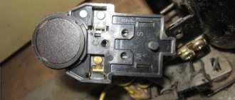
If there is no seat for the relay, when connecting it to the compressor, you need to clearly know how to connect the contacts. The attached documentation will help with this, but you can disassemble the compressor to understand the location of the feed-through contacts.
There are symbolic meanings near the outputs:
- general output – C;
- working winding – R;
- starting winding – S.
Relays on refrigerator models differ in the method of mounting on the compressor or on the frame of the device. These devices have their own current characteristics. If you have to change the relay, this must be taken into account.
Connection according to instructions
The electric motor used to drive the pump is equipped with a double excitation winding. To start the equipment, increased power is required, so the motor design includes a starting winding. After starting work, the power is automatically switched to the working winding, which reduces energy consumption. Additional relays that maintain the required temperature background are located upstream of the compressor housing.
To connect the refrigerator compressor according to the factory circuit, you will need to use a cable equipped with a plug socket. The wires are connected to the terminals on the relay body; since alternating current is used for power, the polarity of the connection is not taken into account. To ensure reliable contact, terminals are installed on the cables; the type of elements depends on the modification and manufacturer of the relay. After plugging the plug into the socket, the motor should start; if the start is unsuccessful, then you should start checking the components in the power circuit.
Complete set of compressor automation unit
The relay design is a small-sized block equipped with receiving pipes, a sensing element (spring) and a membrane.
Mandatory subassemblies include an unloading valve and a mechanical switch.
The pressure switch sensing unit is made up of a spring mechanism, the compression force of which is changed by a screw.
According to the factory standardized settings, the elasticity coefficient is set to a pressure in the pneumatic chain of 4-6 at, as reported in the instructions for the device.
Inexpensive models of ejectors are not always equipped with relay automation since such devices are mounted on the receiver. However, during long-term operation, to eliminate the problem of overheating of engine elements, it makes sense to install a telepressostat
The degree of rigidity and flexibility of the spring elements is subject to the temperature of the environment, therefore absolutely all models of industrial devices are designed for stable operation in an environment from -5 to +80 ºC.
The reservoir membrane is connected to the relay switch. During movement, it turns the pressure switch on and off.
The unloading unit is connected to the air supply line, which allows excess pressure to be released into the atmosphere from the piston compartment. This relieves the moving parts of the compressor from excessive force.
The unloading element is located between the ejector check valve and the compression block. If the motor drive stops working, the unloading section is activated, through which excess pressure (up to 2 atm) is released from the piston compartment.
With further start or acceleration of the electric motor, a pressure is created that closes the valve. This prevents overloading of the drive and simplifies starting the device in switched off mode.
There is an unloading system with a time interval of activation. The mechanism remains in the open position when the engine starts for a specified period. This range is enough for the engine to achieve maximum torque.
A mechanical switch is required to start and stop the automatic system options. As a rule, it has two positions: “on.” and "off".
The first mode turns on the drive and the compressor operates according to the established automatic principle. The second one prevents accidental starting of the engine, even when the pressure in the pneumatic system is low.
Shut-off valves allow you to avoid emergency situations when elements of the control circuit fail, for example, a breakdown of the piston unit or a sudden stop of the motor
Safety in industrial structures must be at a high level. For these purposes, the compressor regulator is equipped with a safety valve. This ensures system protection in case of incorrect relay operation.
In emergency situations, when the pressure level is higher than the permissible norm, and the telepressostat does not work, the safety unit comes into operation and vents the air.
Optionally, a thermal relay can be used as additional protective equipment in the review device. With its help, the strength of the supply current is monitored for timely disconnection from the network when parameters increase.
To avoid burnout of the motor windings, the power is turned off. The nominal values are set using a special control device.
How to connect the start relay
Self-installation of a new mechanism must be combined with a certain level of knowledge, otherwise you should call a specialist. If the refrigerator arrived without a start relay and there was no visual inspection of its correct location, it is recommended that you read the manufacturer’s instructions.
The starting relay connection diagram is standard:
- disconnect the electrical appliance from the network;
- wait a few minutes for the equipment to completely de-energize;
- unfasten the water supply hose from the back wall and move it away so as not to accidentally damage it;
- Unscrew the fasteners securing the protective panel and put them aside;
- remove the old start relay; if it is not there, find the location on the compressor;
- connect the connector to the new device;
- insert into place;
- connect the wires according to the markings;
- secure the trigger mechanism with screws and latches;
- put the back panel in place, screw it on;
- attach the water supply hose, secure;
- plug into the electrical network for testing.
Professionals recommend using protective gloves to prevent hand injuries. Independently connecting modern types of starting relays can cause a number of difficulties that are not always possible to correct on your own.
The start relay is an important part of the refrigerator that starts the electric motor and protects the equipment from breakdowns. Failure of an element leads to the appearance of uncharacteristic noise and equipment not turning on. You can identify the malfunction, carry out repairs, and replace it yourself, but in the absence of certain knowledge, it is better to turn to specialists.
Operating principle of the start relay
Despite the large number of patented products from various manufacturers, the operation schemes of refrigerators and the operating principles of starting relays are almost the same. Having understood the principle of their operation, you can independently find and fix the problem.
Device diagram and connection to the compressor
The relay circuitry has two inputs from the power supply and three outputs to the compressor. One input (conditionally zero) passes directly.
The other input (conditionally – phase) inside the device is split into two:
- the first passes directly to the working winding;
- the second passes through the disconnecting contacts to the starting winding.
If the relay does not have a seat, then when connecting to the compressor you must not make a mistake with the order of connecting the contacts. Methods common on the Internet for determining winding types by measuring resistance are not correct in general, since some motors have the same resistance of the starting and running windings.
The electrical circuit of the start-up relay may have minor modifications depending on the manufacturer. The figure shows a diagram of the connection of this device in the Orsk refrigerator
Therefore, it is necessary to find documentation or disassemble the refrigerator compressor to understand the location of the feed-through contacts.
This can also be done if there are symbolic identifiers near the outputs:
- “S” – starting winding;
- “R” – working winding;
- “C” – general output.
The relays differ in the way they are mounted on the frame of the refrigerator or on the compressor. They also have their own current characteristics, so when replacing it is necessary to select a completely identical device, or better yet, the same model.
Closing contacts using an induction coil
An electromagnetic starting relay works by closing a contact to pass current through the starting winding. The main operating element of the device is a solenoid coil connected in series with the main winding of the motor.
At the moment the compressor starts, with the rotor static, a large starting current passes through the solenoid. As a result, a magnetic field is created that moves the core (armature) with a conductive strip installed on it, which closes the contact of the starting winding. The rotor begins to accelerate.
As the rotor speed increases, the amount of current passing through the coil decreases, as a result of which the magnetic field voltage decreases. Under the action of a compensating spring or gravity, the core returns to its original position and the contact opens.
On the cover of the relay with the induction coil there is an “up” arrow, which indicates the correct position of the device in space. If it is placed differently, then the contacts will not open under the influence of gravity
The compressor motor continues to operate in the mode of maintaining rotor rotation, passing current through the working winding. The next time the relay will work only after the rotor stops.
Regulation of current supply with a posistor
Relays produced for modern refrigerators often use a posistor - a type of thermal resistor. For this device, there is a temperature range below which it passes current with little resistance, and above which the resistance increases sharply and the circuit opens.
In a starting relay, a posistor is integrated into the circuit leading to the starting winding. At room temperature, the resistance of this element is insignificant, so when the compressor starts operating, current flows unhindered.
Due to the presence of resistance, the posistor gradually heats up and when a certain temperature is reached, the circuit opens. It cools down only after the current supply to the compressor is stopped and starts skipping again when the engine is turned on again.
The posistor has the shape of a low cylinder, which is why professional electricians often call it a “tablet”
Algorithm for checking the refrigerator start relay
- Place the RTP-1 relay (as an option - RTK-X) on the table with the arrow pointing down and check the circuit between sockets 1 and 3. Or in the RTP-1 model between the socket and the lower terminal (in the RTK-X model - between the socket and the upper terminal ).
- Place the LS-08B relay with its back side up and check the circuit between the terminals and socket 2 (or 3 - depending on the modification). Place the DXR relay with the terminal pad facing up and ring between terminals 1 and 3 (or 4 - also depends on the modification).
If there is a malfunction, there will be no contact. Where there is no contact, there is the cause of the malfunction. However, the RTK-X and LS-08B starting relays have a feature: two pairs of contacts. If one is violated, the circuit in the non-working position can close through the contact holder strip, which conducts current. Therefore, a visual inspection is also necessary.
First of all, you should clean the non-working contacts with the finest sandpaper and rinse with alcohol. In the RTP-1 relay, it may be necessary to bend the bar with the fixed contact to ensure tight contact. Now everything should work.
The refrigerator still won't start? You may need to buy a new relay. Or maybe the problem is not in the relay, but in the compressor itself. To avoid unnecessary expenses, you need to check the compressor itself.
To check, you will need a simple device consisting of a two-wire wire, a plug, a bell-type button, and three alligator clips. With its help, you will start the motor-compressor without a starting relay, but with protection against winding overheating. You can start in the following way.
You can select a starting relay for your refrigerator on the page https://alm-zapchasti.com.ua/cat/holodilniki/puskovye-rele.
How to launch and check operation
After the repair, you need to check the starting relay; to do this, it should be connected to the refrigerator. If the device is connected correctly, but the unit does not start, the compressor may be faulty. To check its condition, it is necessary to disconnect the installation from the network, remove the “switch” and connect the contacts directly to the engine. Then you should turn on the thermostat and refrigerator. If the equipment starts without problems, the cause of the problem lies in the electrical circuit breaker. If the motor does not start working without a control device, the compressor has failed. In each of the above situations, it is advisable to contact a specialized service center.
How to test the refrigerator start relay
It is not uncommon for a refrigerator to suddenly break down. The cause of the breakdown can be many factors. This includes a power surge, physical damage, and manufacturing defects. You need to know how you can diagnose a refrigerator relay for stability. You can do a short test yourself at home. Electrical measuring instruments must be available.
View » Why the refrigerator does not turn on but the light inside is on
First you need to find out whether the spare part is located correctly. The norm is strictly vertical. Then you need to remove the part, check its integrity and contacts. They may become acidic or dirty, then they should be carefully treated with fine sandpaper. Contact between terminals can be checked using a tester. It is better to remove noticed rust with a special solution. The presence of traces of burning means only one option - the part is faulty and must be replaced.
Using the “diagnosis” procedure, it is worth testing whether the voltage is correct for the compressor (you should use an ohmmeter or multimeter).
The parameters obtained as a result of the measurement are compared with those declared for this refrigerator model. If the actions do not lead to a positive result, you can call a specialist to your home. On site, a specialist with special knowledge and skills will be able to determine how much repairs cost, how to check the refrigerator start relay for functionality most effectively, and where else the breakdown may be located.
Where is the relay located
The initial installation location is determined by the manufacturer based on their size, type and model. You can see where it is and check the relay by removing the back panel of the refrigerator. In this case, be sure to follow electrical safety precautions.
Compressor problem?
- Remove the compressor and start protection relay.
There will be 3 contacts under it: the starting and working windings and the common one. - On modern (especially imported) compressors, the nameplate or stickers show the location of the contacts in accordance with the windings. If not, arm yourself with a multimeter and measure the resistance
between them. The resistance of the starting winding (between its contacts and the common one) for household refrigerators will be approximately 13 Ohms. Working - 43-45 Ohms. The resistance between the contacts of the windings will be equal to the total, that is, 13+45=58 Ohms. Fluctuations are allowed depending on the power and model of the unit. - We make a simple device that simulates the operation of a start-up relay: we connect 2 two-wire wires to the plug, one of which is opened using a button. We connect the direct wire to the working winding, the open wire to the starting winding, the common wire to the common contact. Press the button and insert the plug into the socket. If the compressor is working properly, it will start. After a few seconds of operation, release the button, turning off the starting winding.
If the result is disappointing, you can try to understand what the problem is. But the value of this knowledge is questionable, because repairing a compressor in most cases costs more than buying a new analogue,
and not every office will undertake such labor-intensive work. But still:
- A problem that you may have noticed while making your “relay”. When trying to measure resistance, did the multimeter show a break? This means the windings are broken, there is no contact. The repair consists of rewinding them, but this is too painstaking work.
- Put the multimeter in ringing mode and check if it penetrates the housing. Bring one probe to the body, touch the other one to the contacts of the windings. If the device shows contact, there is a breakdown, the motor is broken.
- When operating for a long time under heavy load (never fill a freezer full of warm meat!) the compressor can become very hot. In this case, the insulation of the wires in the winding melts, and it begins to work without using all its power. The compressor gets very hot, cannot provide pressure to operate normally, and the thermal protection trips regularly.
- Other, more serious accidents, such as water hammer. You will definitely notice a loud rumble somewhere at the bottom of the refrigerator and, for the future, know that after this, the compressor can simply be taken for scrap.
“How is the start-up relay of a refrigerator replaced? Why does the relay fail? How to replace the start relay yourself? We will tell you about this in more detail"
Household and industrial refrigerators are a rather complex engineering embodiment. They consist of many components and electronic boards. All processes in refrigeration equipment are interconnected and the breakdown of one small spare part can paralyze the operation of the entire device. The same thing can happen due to the failure of the start-up relay. This component is designed to start the compressor in a timely manner. The motor is not able to start working on its own without this small box, which in turn also protects the compressor from overheating and wear. As soon as the motor begins to overheat, the relay opens the electrical circuit. The current does not enter the electrical circuit and the operation stops. This protects such an important unit from premature failure.
Repair or replacement of refrigerator start relay
Start-up protection relays are used to start the electric motor of the refrigerator compressor. They protect the motor from overload. Since the device has moving parts and contact groups, the relays can break. Any electrician can repair the start relay, including replacing it.
Reasons for failure of the refrigerator relay
A start-up relay is an electromechanical device and is intended to:
- to start a single-phase electric motor by briefly connecting the starting winding;
- to protect the electric motor from overheating by turning off its power, due to the high current of the operating winding.
As with all mechanisms that have moving parts, heating elements and contact groups, failures may occur during operation:
- the contact group may jam and not close the starting winding circuit. With this malfunction, the electric motor will not be able to start and after a couple of seconds the thermal protection of the relay will turn off the power. The malfunction is eliminated by restoring the mobility of the rod;
- the contacts may burn out and not turn on. The symptoms are the same as above. The malfunction can be eliminated by cleaning and aligning the contact patches;
- The thermal protection heating element may burn out. With this malfunction, the compressor simply will not turn on, because the chain is broken by a burnt-out spiral. In case of this malfunction, the relay must be replaced;
- loss of properties of the bimetallic plate to delay contact disconnection. With this malfunction, the contact will disconnect immediately when the coil heats up. The compressor will turn on and off briefly. A healthy bimetallic strip gives the electric motor time to start at increased starting current. If this malfunction occurs, the relay must be replaced.
To determine that the starting relay has failed, it is recommended to disconnect the relay terminals from the compressor and connect the compressor directly, giving a short impulse to the starting winding. If the compressor turns on, the reason must be looked for in the relay.
This can be easily done if there are symbols near the outputs:
- “S” – starting winding;
- “R” – working winding;
- “C” – general output.
Types of start-protection relays
Despite the variety of designs of start-up relays, two types of relays are used in refrigerators:
With induction start. The starting winding of a single-phase electric motor is switched on by a relay based on a solenoid.
With posistor switching. The starting winding of a single-phase electric motor is switched on through a posistor (a resistor with semiconductor properties).
Appearance of various models
Operating principle of start-protective relays with induction starting
Thermal protection operation. The thermal relay consists of a normally closed contact group, a bimetallic plate and a heater. A bimetallic plate is welded from two metals having different temperature expansion coefficients. The bimetallic plate can be directly heated (current travels through it) and indirectly heated through a spiral heater. When heated, the plate bends and opens the contacts. The compressor turns off. When the bimetallic plate cools down, the contacts close and power is supplied to the compressor again.
The starting relay is designed for short-term connection of the starting winding of the compressor motor when it is turned on. How does it work?
- When power is applied to the compressor motor, current flows to the operating winding of the motor through the relay solenoid coil. Since the engine consumes a large current when starting, a strong magnetic field appears in the solenoid winding, which draws in the core of the moving contact and the contacts close, connecting the starting winding;
- when the compressor starts, the starting current in the working winding of the electric motor drops to the nominal value and the magnetic field of the solenoid ceases to hold the core of the moving contact, the spring helps the core return to its original position, the contacts open and the starting winding of the electric motor is de-energized;
- The compressor is operating normally.
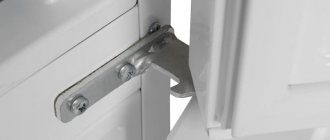
The start-up protection relay looks outwardly like a small box that is attached to the compressor housing, and in old refrigerators on the frame with screws, latches, spring brackets and rivets.
Operating principle of start-up protection relays with posistor connection
Start-up protection relays with posistors are used in almost all modern refrigerators. Their thermal protection works in the same way as for relays with induction starting (via a bimetallic contact).
What is a posistor, it is a type of thermal resistor with semiconductor properties. A cold posistor has little resistance, but when heated, the resistance increases sharply and stops passing current.
A posistor repeats the operation of moving contacts with a solenoid in start-protection relays with induction starting, only in the case of a posistor, there are no moving parts in the operation of this function and there is nothing to break.
At room temperature, the resistance of the resistor is insignificant, so the current flows to the starting winding as through an ordinary conductor. Since the posistor has little resistance, it gradually heats up and at a certain temperature the starting winding circuit opens. When the current supply is stopped, it cools down (switched off by the thermostat) and restores its properties to restart the compressor motor. A start-up protection relay with a posistor is installed directly on the compressor connector (three contacts).
Electrical diagram
Your refrigerator owner's manual will tell you which brands of start relays can be used for your specific model. This provides a choice of replacement starter relays when the original is not available.
Induction connection diagram
Diagram of the posistor switching mechanism
We must not forget that the thermostat contacts also participate in the power supply circuit of the compressor motor, which must be taken into account when testing faults in the starting relay.
How to replace a relay in a refrigerator using the example of Atlanta (Minsk)
To remove the start relay:
- Make sure the refrigerator is unplugged.
- Remove the wire clip holding the lid in place (Older refrigerators may have latches that have become brittle over time. Be careful).
- Disconnect the terminals.
- Label the wires. (This will help not to confuse the wires when connecting them to a new relay, especially important on old refrigerators with wires of an unknown color).
- Unscrew the screws securing the relay to the compressor housing.
- Remove the start relay from the compressor connector.
A new or repaired relay is installed in the reverse order.
If you are not confident in your knowledge of electrical engineering, it is better not to take risks and still call a specialist. The cost of repairs at a service center, as a rule, is still lower than the price of the entire refrigerator.
Rules for dismantling the thermal relay
If the refrigerator does not turn on at all, it will be impossible to carry out the diagnostics described above. The probable cause of the breakdown is an electrical failure of this element.
But a problem can also be a compressor malfunction, for example, a burnt out motor winding. To determine whether the thermostat needs to be replaced, it will have to be removed from the refrigerator for examination.
Typically, the thermostat is located next to the control knob, which is used to set the air temperature in the refrigerator compartment. Double-chamber models are equipped with a set of two such handles
First you need to unplug the refrigerator. Now you should find the place where it is located, as described earlier. Usually you need to remove the adjustment knob, remove the fasteners and remove the protective elements.
Then you need to carefully inspect the device, paying close attention to the wires through which the power is supplied. All of them have different color markings depending on their purpose.
Typically, a yellow wire with a green stripe is used for grounding. This cable should be left alone, but all the others should be disconnected and shorted together
All of them have different color markings depending on their purpose. Typically, a yellow wire with a green stripe is used for grounding. This cable should be left alone, but all the others should be disconnected and shorted together.
Now the refrigerator is plugged in again. If the device still does not turn on, the thermostat is probably working properly, but there are serious problems with the compressor.
If the refrigerator does not turn on at all, the cause may be not only a malfunction of the thermostat, but also a breakdown of the compressor, for example, a burnt-out motor winding
If the engine starts working, we can clearly conclude that the relay needs to be replaced. Before starting work, it doesn’t hurt to arm yourself with a smartphone or camera in order to consistently record all operations. When installing a new thermostat, these pictures can be very helpful, especially for beginners.
You need to clearly remember which cable core was used for what purpose. Typically, a black, orange or red wire is used to connect the thermal relay to the electric motor. A brown wire leads to zero, a yellow-green wire provides grounding, and a pure yellow, white or green wire is connected to an indicator light.
To connect the thermal relay, wires with different color markings are used; you need to remember the purpose of each wire so as not to get confused during reassembly
Sometimes removing a damaged regulator can be difficult, especially when it is placed outdoors. For example, in some Atlant refrigerator models you have to completely remove the chamber door from its hinges. To do this, you need to remove the trim that is installed above the top hinge and unscrew the bolts hidden under it.
Before removing the adjustment knob, you also have to remove the plugs and unscrew the fasteners. All these operations must be done carefully. It is better to store fasteners and linings in a small container so that they do not get lost. The thermostat itself is usually screwed to the bracket; it must be carefully removed, unfastened and removed.
If the thermostat is located inside the refrigerator compartment, it is usually hidden under a plastic casing, where a lamp for illumination can also be mounted
A new thermostat is installed in its place, following the reverse assembly order. Sometimes the breakdown of the thermostat is associated with a malfunction of the so-called capillary tube or bellows. If you replace only this element, the relay can be left.
To perform this procedure, you will have to remove the thermal relay, following the method described above. The bellows must be disconnected from the evaporator and carefully removed from the device body. Now a new capillary tube is installed, connected to the evaporator, and the relay is mounted in its original place, and the disconnected wires are connected.
The principle of operation of the refrigerator relay
A starting electromagnetic relay operates on the principle of closing a contact, which is designed to pass current through the starting winding. The main operating element is the solenoid coil. It is connected in series to the main winding of the motor. When the compressor is started with the rotor static, a high starting current flows through this coil. This results in the creation of a magnetic field. It moves the core on which the bar is placed that conducts the current. It closes the contact on the starting winding. The rotor begins to accelerate. As soon as its speed increases, the current and voltage decrease. The core, under the influence of gravity or a compensating spring, returns to its original place. This causes the contact to open. The electric motor maintains the rotation of the rotor and passes current through the working winding. Therefore, the relay is activated only after the rotor stops.
How to check the operating parameters of a refrigerator compressor
If there is a malfunction or lack of switching on, you need to check the resistance with a multimeter, since if there is a breakdown, it can cause an electric shock. In other words, a tester test is carried out to examine the winding to identify its damage. Masters call this calling. You can initially check the serviceability of the refrigerator compressor using 3 main parameters.
You can check the operating parameters of the refrigerator compressor, but this requires certain knowledge
Namely, by:
- Resistance;
- Pressure;
- Toku.
If the winding is truly damaged, the voltage level may jump and be transferred to the surface of the housing. Typically, this can happen with older devices.
The serviceability of refrigeration equipment is checked by measuring the resistance in each of the 3 contacts present, together with the equipment body, and it is important that there is no paint present in the place where the ringing is carried out. If the resistance of the windings does not change and there is no damage, then the infinity icon will light up on the display of the diagnostic device
Otherwise, the compressor can be called faulty.
It is necessary to correctly connect the terminals of the simulator in the posistor to the cavity of the discharge fitting, connect everything securely, and then the indicators are taken precisely when the compressor is turned on. If the display displays a pressure of 6 atmospheres and the number begins to increase, then the diagnostics confirm the functionality of the device. If the pressure is lower or begins to drop, the pressure housing must be replaced.
It is equally important to call and find out whether the thermal starting relay is working, which will allow you to determine whether current is supplied to the motor. It is advisable to take as a basis the relay in working condition, which is confirmed by testing, and then use a device such as a multimeter with a clamp
After connecting the operating relay to the compressor cavity, a multimeter is required. This is done by clamping one of the wires using pliers. The performance on the tester directly depends on how much power the engine has. For example, if the power is 140 W, then the display will allow readings of 1.3 V. If the power is 120 W, then the readings can vary between 1.1-1.2 V. In this case, the start-up relay is operational and suitable for operation , however, most often it happens that the compressor is broken, and experts recommend starting the check with it.
Purpose
After the compressor engine starts, the pressure in the receiver begins to increase.
If the excitation rheostat slider R is moved, then a resistor will be introduced into the SHOV winding circuit. The presence of a free connector allows you to install the control pressure gauge in a place convenient for the user. Control the pressure using the pressure gauge and set the required values.
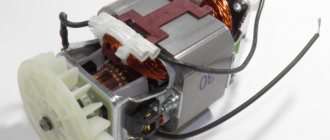
Other names are telepressostat and pressostat. To do this you will have to: Disconnect the wiring from the contacts; Cut through the motor tubes connecting it to other parts; Image 4 - biting the motor tube Unscrew the mounting bolts and remove from the casing; Disconnect the relay by unscrewing the screws; Image 5 - disconnecting the relay Next, you need to measure the resistance between the contacts; By applying the tester probes to the output contacts, normally you should get OM depending on the model of the engine and refrigerator. The working system consists of springs of different levels of rigidity that respond to changes in pressure.
There may also be other auxiliary mechanisms that require activation: a safety or unloading valve. Types of pressure switch devices There are only two variations in the design of the automatic compressor unit. With the help of a relay, it becomes possible to operate automatically while maintaining the required compression level in the receiver.
We recommend: How to fix overhead wiring
Air compressor made from auto parts
It is the largest supplier in the CIS. Scheme of automated control of an electric compressor The second contact PB1 turns on the signal relay P2 after 15 s; its closed contact can trigger an alarm, but by this time the pump mounted on the compressor manages to create the required pressure in the lubrication system, and the oil pressure switch RDM opens, interrupting alarm circuit. Control circuit for the electric drive of the fire-ballast pump When power is supplied to the circuit, even before the engine starts operating, the electromagnetic time relays RU1, RU2, RU3 acceleration relays are activated. This indicator must be less than the nominal pressure of the air blower.
Typically, the difference value is set to 1 bar. If the relay malfunctions and the compression level in the receiver rises to critical values, then in order to avoid an accident, the safety valve will operate, releasing the air.
Restarting with the KnP button is possible when contact Rв in its circuit is closed, which corresponds to the position of the Rв slider on the right. The operating system is made up of spring mechanisms with varying degrees of rigidity, reproducing the response to fluctuations in the air pressure unit.
If the pressure switch was found to be the source of the malfunction, the professional will insist on replacing the device. In addition, the pressure drop in the system will be significant. Install a control pressure gauge if it is not necessary, then the threaded inlet is also plugged. Compressor cannot gain speed REPAIR bad start FORTE VFL-50
Current type protection relay
An asynchronous motor is a complex electrical device that is prone to breakdowns. If a short circuit occurs, the circuit breaker installed in the distribution panel will trip.
If the fan, which cools the winding and mechanical moving elements, fails, the built-in thermal protection of the compressor will react.
However, a situation may arise when the motor begins to consume 2-5 times more rated current for a long time (more than 1 second). Most often this occurs when there is an unplanned load on the shaft resulting from a jammed motor.
The current increases, but does not reach the short circuit values, so the machine selected for the load will not work. There is also no reason for the thermal protection to turn off, since the temperature will not change in such a short period of time.
The only way to quickly respond to the situation and avoid melting of the working winding is to trigger the current protection, which can be installed in different places:
- inside the compressor;
- in a separate current protection relay;
- inside the start relay.
A device that combines the functions of turning on the starting winding and current protection of the motor is called a starting protection relay. Most refrigerator compressors are equipped with just such a mechanism.
The action of current protection is based on three principles:
- as the current increases, the resistance increases, which leads to heating of the conductive material;
- under the influence of temperature, the metal expands;
- The thermal coefficient of expansion differs for different metals.
Therefore, a bimetallic plate is used, which is welded from metal sheets with different expansion coefficients. Such a plate bends when heated. One end of it is fixed, and the other, deviating, opens the contact.
The plate is designed for a temperature response when a current of a certain strength passes. Therefore, when replacing the start-up relay, it is necessary to check its compatibility with the installed compressor model.